10 ENGLISH BOOKS RELATING TO «INDICATOR DIAGRAM»
Discover the use of
indicator diagram in the following bibliographical selection. Books relating to
indicator diagram and brief extracts from same to provide context of its use in English literature.
1
Internal Combustion Engines
INDICATOR DIAGRAM An indicator diagram is a graph between pressure and
volume ; the former being taken on vertical axis and the latter on the horizontal
axis. This is obtained by an instrument known as indicator. The indicator
diagrams ...
2
The
Indicator Diagram: Practically Considered
112 Indicator diagram (high pressure), from a beam engine . . 134 Indicator
diagram (low pressure), from a. beam engine . , 135 Indicator diagrams (high and
low pressure), from a beam engine Indicator diagrams (high and low pressure, ...
3
The
Indicator Diagram Practically Considered
112 Indicator diagram (high pressure), from a beam engine . . 134 Indicator
diagram (low pressure), from a beam engine . . 135 Indicator diagrams (high and
low pressure), from a beam engine 135 Indicator diagrams (high and low
pressure, ...
Nicholas Procter BURGH, 1869
4
A Text Book of Automobile Engineering
INDICATOR DIAGRAM An indicator diagram is a graph between pressure and
volume ; the former being taken on vertical axis and the latter on the horizontal
axis. This is obtained by an instrument known as indicator. The indicator
diagrams ...
5
Engineering Thermodynamics
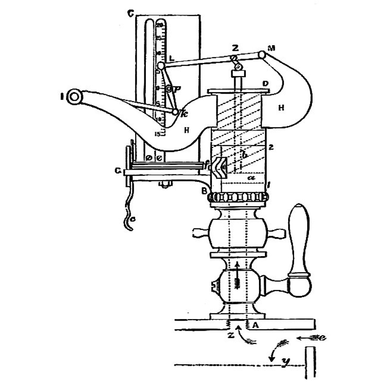
3.3 INDICATOR DIAGRAM An indicator diagram is a trace made by a recording
pressure gauge, called the indicator, attached to the cylinder of a reciprocating
engine. This represents the work done in one engine cycle. Figure 3.11 shows a
...
By turning the indicator cock to a vent position, a horizontal line representing
atmospheric pressure is added to the diagram. This can act as a pressure datum
line. Four types of indicator diagram can be obtained. These are illustrated for a
two- ...
A. J. Wharton, Anthony John Wharton, 1991
The pressure-volume (p-v) indicator diagram is obtained with the help of an
engine indicator. From the indicator (p-v) diagram, the indicated mean effective
pressure (I.M.E.P) is calculated. A planimeter is used to measure the net area of
this ...
8
A Text Book of Fluid Mechanics and Hydraulic Machines
Effect of Acceleration in Suction and Delivery Pipes on Indicator Diagram 996
Solved Problems 20.4-20.9 996 20.8.3. Effect of Friction in Suction and Delivery
Pipes on Indicator Diagram 1004 20.8.4. Effect of Acceleration and Friction in ...
1.4 ACTUAL ENGINES Actual engines differ from the ideal engines because of
various constraints in their operation. The indicator diagram also differs
considerably from the ideal indicator diagrams. Actual indicator diagrams of a two
-stroke ...
10
Internal Combustion Engines
16.3.1 Method using the Indicator Diagram The device which measures the
variation of the pressure in the cylinder over a part or full cycle is called an
indicator and the plot of such information obtained is called an indicator diagram.
Indicator ...